Explanation Of Voltage, Current, and Resistance
This blog post originally started as a planned series, where every week I would go through and summarize a section from the textbook “The Art of Electronics” as a means to learn about electronics.
As I began writing this week's summary on section 1.2, I wanted to explain parts that the textbook glossed over to make sure that I understood what was being written.
This caused the summary to become incredibly long, standing at over 3000 words.
The original title “A Summary of The Art of Electronics 1.2” no longer made sense, and I decided to make this into a general explanation of Voltage, Current, and Resistance.
I plan on continuing to work my way through a section of the textbook every couple weeks, and depending on the length of the section it may be a bit late, but I will try.
If you find any mistakes in my understanding, feel free to email me at jovanycardozaaguilar@gmail.com.
When working with electronic circuits we are mainly tracking two things,
Voltage and Current.
Voltage (V or E) is measured in volt (V).
Voltage is defined as the difference in electrical potential between two points.
Now, what does that even mean?
Let's start with,
What is meant by electrical potential?
Electrical potential, as the name implies, is the potential energy of a point per unit charge.
What is potential energy?
An electrical charge will create electrical fields around themselves, exerting force on the area around them.
This means either a charge needs to do work to move through another charge's field or a charge’s field will do work on another charge pushing/pulling them, depending on if they are the same or opposite charge.
(Note: “Work” is defined as the energy transferred to or from an object by a force acting over a distance. This means that when we talk about work, it is coming from a perspective of energy in a system, rather than just force alone)
What is a unit of charge?
A “unit of charge” is measured in coulombs (C), and is equal to the charge of
electrons, or more usefully known as 1 ampere of current (we will define this later) for one second, and in-turn a current of one amp equaling a flow of one coulomb of charge per second.
The force between two charges is a combination of the strength of the two charge’s electrical fields and their distance from each other.
The equation for finding the force of two charges at a specific point in time is through Coulomb's law,
F is the force between the two charges, k is a universal constant of the strength of interaction between charged particles,
q1 and q2 is the amount of charge for each particle, and r the distance between the charged particles.
This is NOT the potential energy between two points and does not give us the voltage, but it is a step on the way to finding the voltage.
This equation gives us the force for a static moment in time between two charges; to find the total potential energy between the two points, we need to know the force at every step of the way as the two points come closer together until they meet.
This seems like it would be a difficult problem and would take a lot of calculations,
How can we calculate what is essentially an infinite amount of steps between two points?
Well, if you remember what you studied in calculus, this should sound familiar.
We can use an integral!
All have to do is take Coulomb's law and integrate it,
(electrical potential energy)
The negative sign is typically dropped or added to the sign of the charges, either way the interaction between charges would be unchanged simply changing the math to have flipped signs, leaving us with the equation,
With this we can properly define a voltage.
First, let's imagine two points A and B.
We calculate what the electrical potential energy is for each point
where q2 is the test charge against point A to find its electrical potential energy,
and we do the same with point B,
Now that we have the electrical potential for both points we simply subtract them from each other to find the voltage,
(Note: Notice how the equation has opposite charges produce higher voltages and lower voltages if they are the same charge)
Now that we have defined a volt we can begin defining other terms.
A joule (J) is defined as the amount of work/energy used to move a coulomb across a potential difference of one volt.
Current (I) is the rate of flow of electrons measured in ampere/amp (A).
(Note: By convention, current in a circuit flows from positive to negative, even though actual electron flow is in the opposite direction)
As we can see from these definitions, current flows through a path, while voltage is the difference between two points and is not “flowing” through a path.
We generate voltage by doing work on charges by converting some type of energy (electrochemical, mechanical energy, etc.) into a point so that its electrical potential energy increases.
We then connect it to another point with lower electrical potential energy utilizing the voltage (electrical potential difference) to get the charge/current flowing.
Here are some useful rules to keep in mind for when dealing with circuits in series/parallel,
- Kirchhoff’s Current Law (KCL), the sum of the currents into a point in a circuit equals the sum of the currents out.
- Kirchhoff’s Voltage Law (KVL), the sum of the voltage drops around any closed circuit is zero.
A resistor is defined by its resistance (R) measured in ohms (Ω), described by Ohm’s Law,
A resistor restricts charge flow, along with absorbing and dissipating electrical energy as heat, lowering voltage across it.
This makes it useful for converting voltage to current,
and current to voltage,
(Note: Notice how they are all variations of Ohm’s law)
To find the amount of power dissipated by a resistor, we must first know the equation for the power dissipated by any device.
First, power (P), measured in watts for our purposes, is defined as the rate of work/energy transfer in joules (J) per unit of time (t) in seconds.
and earlier we defined volts as,
and since W and U both represent the same joules of energy, in different context we can define the equation as,
and as current is just the flow of charge per time we can define it as,
when we multiply the volt and current equation we get,
which is exactly the same as the power equation! That means we can write power as,
We can use this to find the amount of power dissipated from a resistor by plugin in Ohm’s law,
When you know the current, but not the voltage
When you know the voltage, but not the current
You can use it directly if you know both current and voltage, as current and voltage are dependent on the resistance.
When we put resistors in series (in a row), each successive resistor will further increase resistance.
This can be thought of, and equivalent to a single large resistor,
We use this equation as, by Kirchhoff’s Voltage Law, the dropped voltages from the resistors will sum to be the same as put into the system.
meaning
We are able to bring out the
for
as Kirchhoff’s Current Law states that the sum of current into a point will be the same as the output, and as the circuit is in series the current will be the same for the whole circuit.
When we put resistors in parallel (side by side), we are creating more paths for the current to flow, even high resistance resistors will continue adding to the total current flow, as total current increases and voltage remains the same it follows by
that total resistance falls.
We use this equation as, by Kirchhoff’s Current Law, the current flowing in should sum up to be the same amount flowing out.
We then move
to the other side, solving for
meaning
We are able to bring out the
for
as Kirchhoff's Voltage Law states that the sum of voltage drops around any closed circuit is zero, and as the circuit is in parallel the voltage will be the same for all paths.
Some may find it helpful to think in terms of conductance,
Then plugging it into Ohm’s law replacing
we get,
The unit of conductance is the siemens
also known as the mho (ohm backwards).
Electronic circuits accept some sort of applied input (usually voltage) and produce some sort of corresponding output (usually voltage), this is called the transfer function H, the ratio of (measured) output divided by (applied) input.
A voltage divider is a circuit that takes an input voltage and produces an output voltage that is a fraction of the input voltage. They are used to generate a specific voltage from a larger voltage.
We can create a simple voltage divider circuit by placing two resistors in series, and we can find the output voltage between the two resistors,
First, we find the current,
Then, we can just plug it into the equation for voltage to get the output voltage, with
being the resistance as we are looking at the point between the two resistors, meaning we are already past the first resistor
we can rewrite this as,
which is the transfer function H for this circuit.
Thévenin equivalent circuit, Thévenin theorem states that any two-terminal network of resistors and voltage sources is equivalent to a single resistor in series with a single voltage source.
This means that any combination of batteries and resistors can be mimicked with one battery and one resistor (in a two-terminal network).
To build an equivalent circuit, we need two things: the open-circuit voltage () and total resistance of between two terminals ().
What is open-circuit and short-circuit voltage?
An open-circuit voltage is the electrical potential difference (i.e. voltage) between two terminals, imagine a battery and the voltage between the positive and negative end.
(open circuit)
A short-circuit is the maximum possible current between two terminals.
We can find the maximum current between two terminals through Ohm’s law,
(short circuit)
and in-turn, we can rewrite the equation to find
As an example, let's take the voltage divider circuit we used earlier looking at the point between the two resistors.
The open-circuit voltage is,
The short-circuit current is,
as it is short-circuited
is not interacted with and left out of the equation
So the Thévenin equivalent circuit is a voltage source,
in series with a resistor
(Note: It is not a coincidence that this happens to be the parallel resistance of and )
This is all assuming there is no device/load resistor connected, what happens when we actually connect something?
What happens is that the load will run in parallel with and total resistance falls which increases current, causing to absorb and drop the voltage below what is expected by the ideal unloaded voltage output.
From a Thévenin perspective this is due to the source resistance (Thévenin equivalent resistance of the voltage divider output, viewed as a source of voltage).
(Note: The terms source resistance, internal resistance, and Thévenin equivalent resistance all mean the same thing)
There are different approaches to dealing with this issue, one is to use much smaller resistors in a voltage divider. Lower resistance will reduce but will waste more power as heat.
However, it is usually best to construct a voltage source/power supply, using active components like transistors or operational amplifiers.
This allows for a voltage source with internal (Thévenin equivalent) resistance as small as milliohms (thousandths of an ohm) without the large current and lost heat from low-resistance resistors.
What would happen if I attach a load that has a resistance less than or similar to the internal resistance?
We can determine this from a Thévenin perspective,
As we can see the larger the load resistance, the less the internal resistance matters leading to only a small reduction in output voltage, and a small load resistance leading to significant reduction of output voltage.
(Note: circuits are ordinarily designed so that the load resistance is much greater than the source resistance of the signal that drives the load)
You may have noticed that all these equations assume that the resistor will have a current (I) that is proportional to applied voltage (V); this is called a linear resistor. But, we often deal with electronics devices where I is not proportional to V; it will be more useful to know the slope of the V-I curve to calculate resistance.
This can be written as the ratio of a small change in applied voltage to the resulting change in current through the device,
or
This is called the small-signal resistance, incremental resistance, or dynamic resistance.
An example of non-linear I-V curve is a zener diode, a zener is used to create a constant voltage inside a circuit.
The figure is attached below that shows that it blocks all current until the voltage reaches a certain level (zener voltage), and keeps it at that voltage level (until it exceeds its power rating)
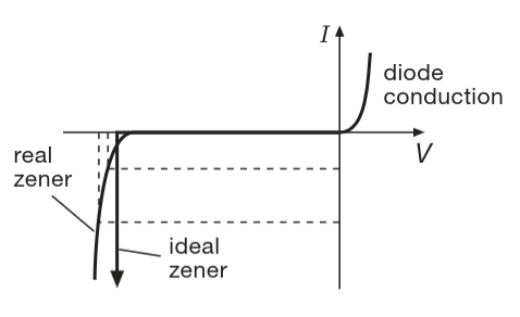
In real life, the applied current is never perfectly steady and will fluctuate.
How well the zener diode can handle changes in driving current is called “regulation”, which will be included in the zener’s specification called dynamic resistance, given at a certain current.
Let’s take a zener with a dynamic resistance of 10Ω at 10mA, at its specified zener voltage of 5V.
Imagine there is a 10% fluctuation in the current, using Ohm’s law with dynamic resistance,
Or
thus demonstrating good voltage-regulating ability.
A zener often gets its current through a resistor from a higher voltage in the circuit.
We can find the voltage output by first finding the current,
And since in real life the voltage fluctuates we use dynamic resistance,
Then using Ohm’s law with dynamic resistance,
It’s the voltage-divider equation, again!
This means for changes in voltage, the circuit behaves like a voltage divider, with the zener replaced by a resistor equal to its dynamic resistance at the operating current.
A useful fact, when dealing with zener diodes, is that the dynamic resistance of a zener diode varies roughly in inverse proportion to current.
There are ICs designed to substitute for zener diodes, known as “two-terminal voltage references” that have much lower dynamic resistance and excellent temperature stability.
A zener will provide better regulation if driven by a current source, but current sources are more complex, and in practice we use a resistor.
(Note: When working with zeners, it’s worth remembering that low-voltage units (e.g. 3.3 V) behave rather poorly, in terms of constancy of voltage versus current, use a two-terminal reference instead)
And that’s it for this week!
The next post will be covering section 1.3 on signals.